Database Design
_____ , , _____Database Design is a systematic approach that establishes how information is kept, retrieved, and controlled. In order to create a strong and effective database structure,it needs three main stages: conceptual, logical, and physical design.
Conceptual database design
The first stage, known as conceptual database design, determines the key data components, their connections, and related limitations. It serves as the basis for the logical and physical design phases that follow by encapsulating the organization's business principles in a high-level abstract model.
In particular, entities and their properties are identified using conceptual database design. Entities, like Student, are representations of actual things or ideas, whereas attributes, like Name and Student_ID, explain their characteristics.The following procedures are commonly employed to put conceptual database design into practice:
- Gathering Requirements: to understand the essential data pieces and their applications, start by gathering comprehensive business requirements. This step entails working with stakeholders to determine the database's scope and purpose, making sure that the design satisfies user requirements and organizational goals.
- Identify Entities and Attributes: identify the main entities that are pertinent to the system, such as clients, goods, or orders. List the attributes of each entity, such as a customer's name, address, or phone number, which are particular facts that define or characterize the entity.
- Define Relationships:This involves defining the kind of relationship (one-to-many, many-to-many, or one-to-one) as well as any limitations or guidelines that may apply to these exchanges.
- Creating an Entity-Relationship Diagram (ERD):to visually depict entities, their characteristics, and the connections between them, use entity-relationship modeling. As a conceptual database blueprint, the ER diagram aids in clearly communicating the structure and pointing out possible design flaws.
- Review and Feedback:show the conceptual model to stakeholders for validation, including developers, users, and business analysts. To make sure the model appropriately captures real-world requirements, get their input. Before proceeding to the logical and physical database design phases, make the necessary changes based on their feedback to enhance and improve the design.Using Student, Teacher, and Department Entities as an Example
Requirements Gathering
- Students enroll in departments.
- Teachers belong to departments.
- Teachers teach students.
Identify Entities and Attributes
- Department_ID, Department_Name
- Student_ID, Name, Email
- Teacher_ID, Name, Email
Define Relationships
- Department has many Students,which is one-to-many.
- Department has many Teachers,which is one-to-many.
- Teachers teach Students,which is many-to-many.
Entity-Relationship Modeling
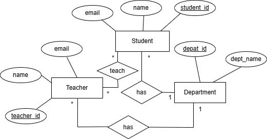
Review and Feedback
- Finally, we discussed the final ER diagram with stakeholders to ensure it accurately reflects requirements and revised it as needed.
Logical database design
Logical database design is the process of creating a comprehensive data model that accurately represents an organization's data structure.The following are the primary tasks involved in logical database design.
- Making a logical model out of the conceptual ER diagram.
- Establishing Primary and Foreign Keys are defined to enforce relationships between tables, and primary keys are assigned to uniquely identify records.
- To remove redundancy, apply normalization and arrange data into well-structured tables.
- Defining Data Types and Restrictions Decide on suitable data types.
- Business rules should be documented and converted into database constraints.
- Prior to physical implementation, review and validate the logical schema with the appropriate person to make sure it satisfies criteria.
For instance,Mapping the Conceptual Model
- Student(Student_ID, Name, Email, Department_ID)
- Department(Department_ID, Department_Name)
- Teacher(Teacher_ID, Name, Email,Department_ID)
- Teaching(Teacher_ID, Student_ID), to represent many-to-many relationship
Defining Primary and Foreign Keys
- Department_ID: primary key in Department
- Student_ID:primary key in Student
- Teacher_ID:primary key in Teacher
- Teaching uses a composite primary key: (Teacher_ID, Student_ID)
Foreign Keys
- Student.Department_ID: Department.Department_ID
- Teacher.Department_ID: Department.Department_ID
- Teaching.Teacher_ID:Teacher.Teacher_ID
- Teaching.Student_ID:Student.Student_ID
- Applying Normalization:Normalize all tables up to 3NF
Specifying Data Types and Constraints
For Student:
- Student_ID INT PRIMARY KEY
- Name VARCHAR(100) NOT NULL
- Email VARCHAR(100) UNIQUE
- Department_ID INT NOT NULL
For Department
- Department_ID INT PRIMARY KEY
- Department_Name VARCHAR(100) NOT NULL
For Teacher
- Teacher_ID INT PRIMARY KEY
- Teacher_Name VARCHAR(100) NOT NULL
- Email VARCHAR(100) UNIQUE
- Department_ID INT NOT NULL
Note: A teaching table, also known as a junction table, links the primary keys of two related tables to simulate a many-to-many relationship.
Physical database design
Converting the logical data model into tangible structures that are tailored for a particular database management system is known as physical database design. It emphasizes performance, dependability, and scalability in the way data is stored, indexed, and accessed.Key Steps in Designing a Physical Database
- Table Structure Definition: To convert the logical database model into actual physical tables, specify the relevant data types and comprehensive column definitions.
- Building Indexes: By accelerating data retrieval procedures, indexes can be used to improve query efficiency.
- Defining Constraints: To guarantee the precision and consistency of the data, use rules like PRIMARY KEY, FOREIGN KEY, UNIQUE, NOT NULL, and CHECK.
For example,Define Table Structures with Data Types and Constraints
CREATE TABLE Department (
  Department_ID INT PRIMARY KEY,
  Department_Name VARCHAR(100) NOT NULL
);
CREATE TABLE Teacher (
  Teacher_ID INT PRIMARY KEY,
  Name VARCHAR(100) NOT NULL,
  Email VARCHAR(100) UNIQUE,
  Department_ID INT,
  FOREIGN KEY (Department_ID) REFERENCES Department(Department_ID)
);
CREATE TABLE Student (
  Student_ID INT PRIMARY KEY,
  Name VARCHAR(100) NOT NULL,
  Email VARCHAR(100) UNIQUE,
  Department_ID INT,
  FOREIGN KEY (Department_ID) REFERENCES Department(Department_ID)
);
Implement a Many-to-Many Relationship Using a Junction Table
 CREATE TABLE Teaching (
 Teacher_ID INT, Student_ID INT,
 PRIMARY KEY (Teacher_ID, Student_ID),
 FOREIGN KEY (Teacher_ID) REFERENCES Teacher(Teacher_ID),
 FOREIGN KEY (Student_ID) REFERENCES Student(Student_ID)
 );
Indexing for Performance
 CREATE INDEX idx_student_email
 ON Student(Email);
 CREATE INDEX idx_teacher_email ON Teacher(Email);
 CREATE INDEX idx_teaching_teacher
 ON Teaching(Teacher_ID);
 CREATE INDEX idx_teaching_student ON Teaching(Student_ID);
Latest Posts

Top 9 Web hosting Companies in Ethiopia.

File Handling in Java.

Online Communication Platform for Teachers and Students.

I’m committed to providing tailored solutions and always ready to assist if any issue arises.